|
The Michelson-Morley Experiment: © Ferenc Kiefner, 2005
This is an HTML page from location http://www.kiefner.hu/view/mmximp.htm
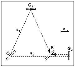
By means of the Michelson interferometer a number of experiments were carried out to demonstrate the translational motion of the earth. The author re-analyzes the method of calculation in these experiments, and shows that, when taking into account a factor so far judged negligible, the expectable total phase shift will be proportional to the fourth power of v/c (the ratio of translation speed to light velocity). 1. Introduction More than a century has elapsed since 1887 when A. A. MICHELSON and E. W. MORLEY conducted their famous experiment [1], which was expected to reveal the translational motion of the earth. Although this experiment was repeated many times in the course of the years with the use of increasingly more sensitive equipment, no success could be attained in a reliable demonstration of the translational motion of earth. In addition to the experiments carried out with the use of the Michelson interferometer, experiments based on other methods have been conducted for the detection of this motion, but each of these also had a negative result or at least, a disputed one. All these facts, however, do not exclude the possibility of making another analysis of the mentioned experiments on the basis of appropriate considerations. Of these, the author has selected the Michelson-Morley experiment as that to which a great conclusive force can be attributed, and, he now suggests an improved method of calculation. Although the differences existing between the traditional and improved methods of calculation will be pointed out in several places, this article is not intended to give a comprehensive critique of the traditional method. The author's purpose is merely to draft a possible theoretical structure for calculation of arising phase shift. It should be mentioned in advance that no hypothesis relating to the existence of a physical phenomenon or law unknown to date will be cited in this article. As the Michelson-Morley experiment is well known, the related path calculation method will be described only in a concise summary in the Appendix, and the formulae and figure reported there will be referred to with the letter A preceding their reference numbers. A scheme of the Michelson interferometer is shown in Fig. 1 in a position in which one of the arms - let this be K2 - is parallel to the direction of motion. 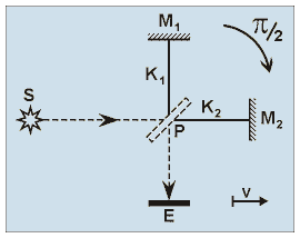
Figure 1. Scheme of the Michelson interferometer.
  
When the interferometer used in the experiment is rotated through angle π/2, and one of the arms is parallel to the direction of motion in the initial and final positions (hereafter called main positions), according to traditional method the value of total phase shift arising between the rays travelling along the arms can be expressed in radians as follows:
For the sake of historical completness, it may be mentioned that in 1881, when Michelson and Morley first attempted to demonstrate the earth's translational motion in an experiment, they used twice larger value for awaited total phase shift
since the path of light perpendicular to the direction of motion was mis-modelled. On the basis of M. A. POTIER's comment, that error was corrected [3] in paper [1]. According to the improved method of calculation suggested by the author, the total phase shift will be calculable with the use of the formula
that is, the arising overall fringe shift in interference pattern will be proportional to fourth order effect in v/c. In the following, we shall discuss how the formula (1) can be derived. 2. Inaccuracy implied in the traditional method of calculation The progression of the interfering rays in the moving interferometer is shown in Fig. 2. The paths of rays are depicted in accordance with the traditional model. Those rays that propagate along the arms here are illustrated and only the positions of mirrors M1, M2 and the semi-transparent mirror P are indicated. 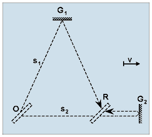
Figure 2. A model of light paths employed in the traditional method of calculation. According to this model, in the interferometer moving with translational speed v the light rays starting from the same position in the space will return to a common point.
  
For the paths traversed, the following relationships can be written on the basis of formulae (A‑5) and (A‑6):
Thus, the sine waves of light arriving at point R from point O at moment tR are described by the following equations:
The rays emerge from a common light source, and for this reason the initial phases of the oscillations in the equations of the rays are identical. For the sake of simplicity, the initial phases have been taken for zero in the equations of the rays. This simplification will be employed later as well. Subsequently, in addition to the commonly used concept of the initial phase the term "start phase of the ray" will be introduced as an auxiliary concept. For this reason it is considered very important that even now a clear discrimination should be made between the two concepts. In Fig. 2, the ray progressions shown in the model tacitly assume that the light rays starting from an the same (point O) of the moving mirror P and travelling strictly along the arms will return to a common location (point R). Let us now show that this assumption in the model, as shown in Fig. 2, generally leads to an inaccuracy.
Likewise, the light ray advancing along arm K2 at velocity c covers path s2 during a time t2. In this time interval, mirror P moving at velocity v covers a path of
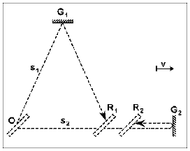
Taking this fact into consideration, the accurate ray path of the traditional model can generally be illustrated as shown in Fig. 3. 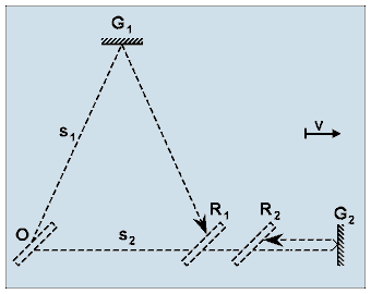
Figure 3. Analysis of the velocity and path conditions reveals that generally the return point of light rays starting from the same location can be different. This fact has already been pointed out by Michelson and Morley, but they decided its effect negligible.
  
According to the earlier analysis, the lengths of sections OR1 and OR2 are:
According to the earlier analysis, the lengths of sections OR1 and OR2 are:
In a given position of the interferometer the length of these two sections could be equal only when a relationship of
exists between the lengths of the arms. However, upon rotation of the interferometer, the equality of sections OR1 and OR2 ceases to exist even in the case of the existence of the aforementioned relationship. According to this, since the two sections are not generally equal, point R splits into points R1 and R2. The question detailed above was also mentioned [2] in article [1]. However, in the absence of any detailed numerical assessment thereof, its effect was considered negligible. The relevant literature seems to be uniform in discussing the principles of method of calculation applied with the Michelson interferometer. It ignores the apparent possibility of inaccuracy, or rather, it does not even make mention of it. For this reason, the references are limited to article [1], since it has already revealed the possible source of inaccuracy. The problem becomes particularly acute, if the lengths of the arms (l1, l2) differ greatly from each other. Then, the lengths of light paths (s1, s2) may also be considerably dissimilar with each other. Consequently, the distance
existing between the returning light rays could also be increased significantly. In such a case, if a point-like test object were placed between the light source and mirror P, a doubling of the image of the test object, in compliance with the traditional model, would become possible upon sufficient change in translation velocity. To summarize, it seems to be expedient to make a proposal for a model that excludes the previously revealed possibility of inaccuracy, or one that can be employed in the case of an arbitrary arm length and velocity. 3. The proposed model and method of calculation Accurately retaining the path length of the rays (s1, s2), we must correct the traditional model so that the above mentioned possibility of inaccuracy will not occur in the modified model. The proposed model, shown below in Fig. 4, attempts to fulfill these requirements. 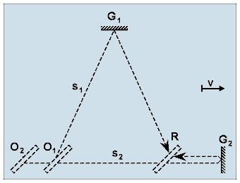
Figure 4. Model of the light paths applied to the improved method of calculation. The corrected model permits rays returning to a common point to start from different points in space. At the same time this also implies that the start phases of the two light rays can differ from each other. The possibility of inaccuracy inherent in the traditional method can be eliminated by using this model.
  
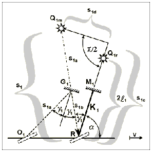
While in the traditional model (shown in Fig. 3) the rays propagating strictly along the axes started from the same point O but arrived at different spatial points R1 and R2, these rays return to the same point R in the proposed corrected model. As a consequence of this, the previously mentioned possibility of inaccuracy cannot occur regardless of the length of the arms or the speed of the translational motion. In the revisited model, however, it has to be taken into account that the rays returning to point R may start from different positions of the moving mirror P (points O1 and O2) and, consequently, at different moments in time. Therefore, the start phase of these rays can differ by some ωΔt, where Δt is the difference between the starting times of the rays outgoing from points O1 and O2. Thus, not only is the change in spatial conditions (path lengths) taken into account among the consequences of motion, but the traditional method of calculation is enhanced by regarding the altered time conditions (start phases) as well. The same evident procedure employed by the traditional method will be used to calculate the path lengths of the light rays. The method of calculation in this article will be improved only by determining the difference of start phases ωΔt of the light rays outgoing from points O1 and O2. Here, ω is constant and known and thus the unknown Δt has to be calculated. In the course of the calculations it should be naturally requested that in the case of v → 0 each of the formulae should be transformed into generally accepted formulae or should adopt those values, that this formulae give for resting interferometers. The reader can check the fulfillment of this requirement later. The interferometer will be broken down into two subsystems, one each for arms K1 and K2, for the calculations. The quantities of the individual subsystems will, as previously, be distinguished by subscripts 1 and 2. To unite the two subsystems the time moment tR, when the arms just pass through the point R, was chosen as the common reference point for the time-counting. In what follows, the path of a ray in one of the subsystems, let this be the arm K1 subsystem, will be studied in detail. To this end, a ray that travels along the appropriate axis in an arbitrary position of the interferometer, will be plotted on the basis of Fig. A-1. In this position the arm K1 subtends angle α with the direction of motion, and the characteristics of light ray can readily be examined. To facilitate the analysis, the light source is assumed to be located directly at mirror P which is rigidly connected with the arms. Fig. 5 shows the equivalent image of the light source, which can be observed at point R. This image is considered a virtual light source. 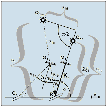
Figure 5. Path of a light ray travelling along arm K1 of the interferometer in case of an arbitrary angle α. In order to achieve a surveyable illustration and facilitate the calculations, the path of a ray is shown as outgoing from the virtual light source, which can be observed at point R. With the interferometer at rest, a light ray would travel a path of 2l1 in length along the arm. When the interferometer is moving, the path of light becomes elongated
(s1 > 2l1), and it subtends angle γ1 with the arm.
  
We shall investigate the position of the virtual light source in two different states of motion. In the figure Q1r denotes the position of virtual light source in a resting interferometer (v = 0), while Q1m marks the position of virtual light source in a moving interferometer (v > 0). For a better demonstration of the spatial positions Q1r and Q1m of virtual light source, a prolonged line is drawn along arm K1 with a short break in continuity. With the interferometer at rest, the virtual light source would constantly be located in point Q1r on the prolonged line of arm K1, i.e. at moment tR it can also be found there. At this time the light ray starting from point Q1r could be described in point R and at moment tR by the equation
When the interferometer is moving at speed v, the light ray in point R and at moment tR is not represented correctly by the above equation because
To sum up, it may be stated that the path of the light ray not only lengthened (s1 > 2l1) but also "turned back" from arm K1 around point R (γ1 > 0), and, thus, the light source Q1m has arrived behind the prolonged line of arm K1. According to the above reasoning, in the case of a moving interferometer the light ray is described correctly in point R and at moment tR by the equation
This formula reflects the fact that in point R the phase of the ray is affected by the lengthened path (Δl1) as well as the changed start phase (ωΔt1) on account of the light ray's deflection.
Since the value of s1 is already familiar from formula (A-1), Δl1 will not be discussed separately. Accordingly, for further calculations it may be written that
Let us now determine the value of the unknown time interval Δt1 . To this end, with reference to Fig. 5, let us break path s1 into two components:
When the value of component s1d is zero, i.e. when the virtual source is located on the line of arm K1, the value Δt1 obviously will also be zero. (This also holds true when simultaneously s1c > 2l1, which is possible if α = 0 and v > 0.) On the basis of this, it can be stated that the appearance of the time interval Δt1 is due to the spatial distance s1d arising between the virtual light source Q1m and the line of arm K1. The light ray covers the path s1 during a time
Should the light travel along s1c, time interval t1c would require:
An unknown supplementary interval Δt1 must be added to time interval t1c to obtain time interval t1, during which the light ray can cover path s1. Thus, with interval Δt1 added, the component s1d, which is perpendicular to the arm, is created in addition to the component s1c coinciding with the direction of the arm:
According to the geometry of Fig. 5, the length of s1c is
With t1, t1c and s1c eliminated, the unknown Δt1 can be obtained from the above set of four equations as a function of quantities s1 and γ1.
On the basis of relationship (A-2), this may also be written as
Notably, in the case of α = 0 (arm K1 is parallel to the direction of motion) Δt1 will assume a zero value at any velocity, since the light ray does not deflect laterally from the arm. An entirely analogous procedure can be adopted in investigation of a ray travelling in the arm K2 subsystem. Thus,
As previously, let us introduce the notations
in the formulae (2) and (4), where Φ1 and Φ2 are the phases of light rays returning to point R at moment tR.
where Δt1 ‑ Δt2 = Δt gives the difference between the starting times of the rays outgoing from points O1 and O2.
By substituting here the values of s1 and s2 from expressions (A-1) and (A-3), Δt1 and Δt2 from expressions (3) and (5), cos γ1 and cos γ2 from expressions (A-2) and (A-4), and by using relationship
Assuming that β << 1, let us expand the expressions
By using (7) and the earlier introduced notation k = 2π(2l1+2l2)/λ, formula (6), which supplies the value of the total phase shift ΔΦΣ, may be written as follows:
Thus, formula (1), which was presented earlier in this paper, has been completely deduced.
APPENDIX
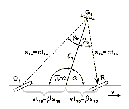
Let us examine the paths of rays that travel strictly along the arms, with the interferometer in an arbitrary position, when arm K1 subtends angle α with the direction of motion. The interferometer is moving at the rate of speed of v, and the arms K1 and K2 have a length of l1 and l2, respectively. The path of a ray of arm K1 is indicated in Fig. A-1. For simplification of the formulae, let us stipulate that 0 ≤ α ≤ π/2. 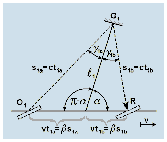
Figure A-1. The path of a ray of arm K1 in the interferometer moving with translational speed v. Arm K1 with length l1 subtends an arbitrary angle α with the direction of motion.
  
Let us determine the quantities s1a, s1b, γ1a and γ1b (giving the path lengths and inclination angles of the ray) as the functions of quantities l1, α and β. Determination of the quantities sought is a simple geometric task; however, for the sake of completeness, the calculations are given below.
From the foregoing, the total length of the path of a ray from point O1 to point R is
On the basis of the sine law, it may be written that
From the above expressions
and, in what follows, γ1 will be written instead of γ1a and γ1b. Hence,
The path of a ray can be calculated in a perfectly analogous way for arm K2. The only difference is that arm K2 subtends angle α - π/2, not α, with the direction of motion. Accordingly,
By substitution α = π/2 into (A-1) and (A-3), the length of the paths will be obtained for the interferometer in the position shown in Fig. 1:
References
Symbols used in the paper Symbols beginning with Roman characters:
Symbols beginning with Greek characters:
|


